


AIKON Article Details | AIKON
How to use a single frequency converter to control high and low water levels
2025-02-28 17:01:06

How to Use a Single Frequency Converter to Control High and Low Water Levels?
Abstract
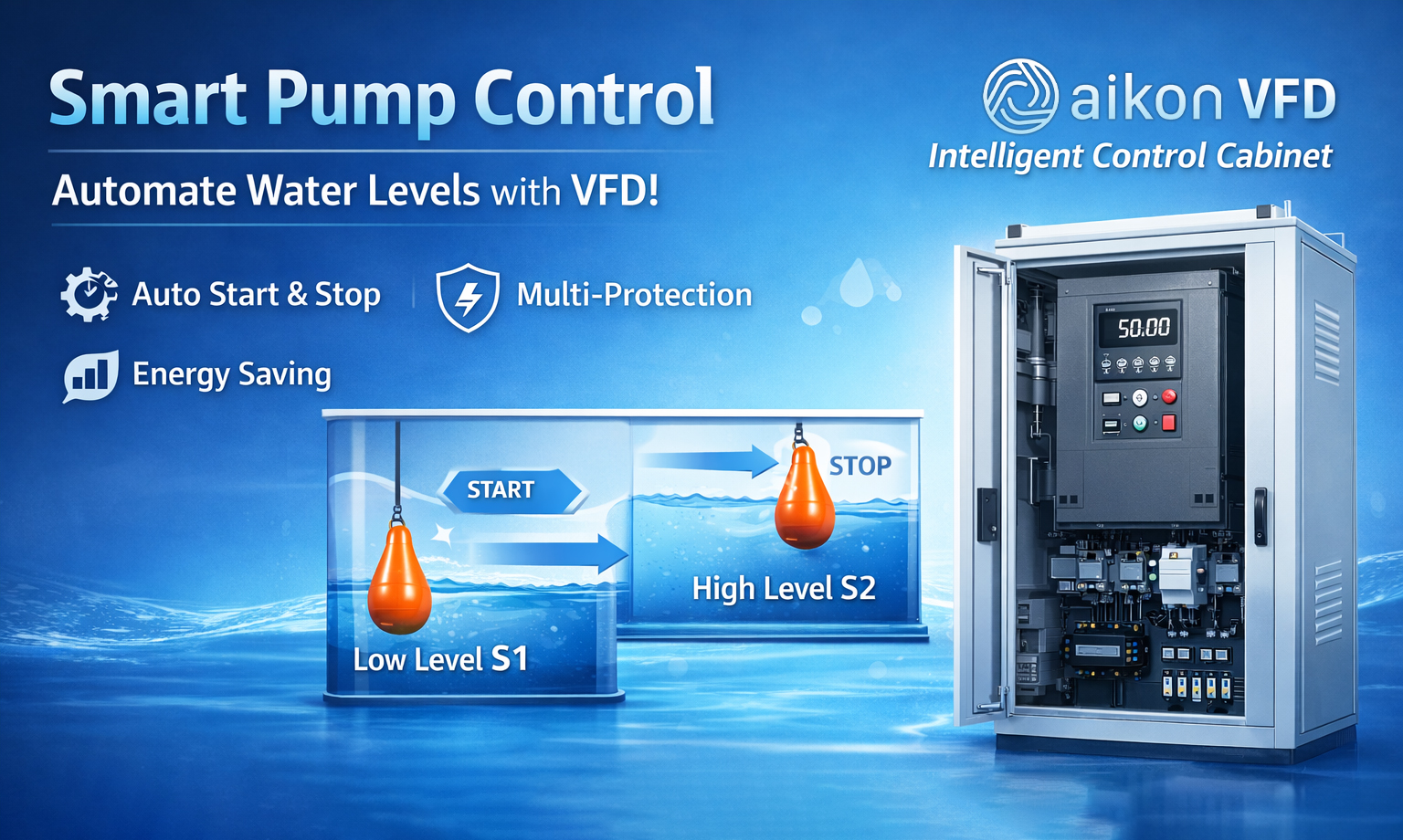
Imagine if the pump could automatically start and stop based on the water level, avoiding manual adjustments and making the system more stable. By using a Variable Frequency Drive (VFD) and float switches, we can achieve automatic water level control. It's like giving the pump an intelligent “brain” that starts the pump when the water level is low and automatically turns it off when the water level is high, keeping the water at an ideal level.
How to Wire It?
1. Wiring the Float Switches
You will need two float switches, which act like the pump's “command followers.”
Low Water Level Start: The first float switch (S1) is used to detect when the water level is too low. When the water drops below the set value, S1 closes the circuit, just like pressing the "start" button, telling the VFD to turn the pump on.
Wiring: Connect one terminal of S1 to the RA terminal of the VFD and the other terminal to the RB terminal, while also connecting it to the DCM terminal. This is like connecting a switch to a battery and a light bulb circuit to turn the light on.
High Water Level Stop: The second float switch (S2) detects when the water level is too high. When the water level rises to the high set point, S2 opens the circuit, sending a stop signal to the VFD, turning off the pump.
Wiring: Use the normally closed (NC) contact of S2 to connect to the DCM terminal. When the water level reaches the high point, this signal tells the VFD to stop.
-------------------------------------------------------------------------------
How to Set the VFD Parameters?
To allow the VFD to respond to the signals from the float switches, you need to set the following parameters:
F06.00 = 1: Enable external terminal control, so the float switches control the pump's start and stop.
F06.01 = 6: Set the port for the start/stop signals, telling the VFD which signals control the pump.
F03.03 = 18: Set the stop command mode, so the VFD knows when to stop the pump.
F00.01 = 1: Enable the external terminal control feature, allowing the float switches to control the pump.
----------------------------------------------------------------------------------
How It Works: Control Logic
Control Logic:
When the water level drops below the set low point, S1 closes, sending a signal to the VFD to start the pump. It’s like pressing the "start" button when the water level is low, and the pump starts running.
When the water level rises to the high set point, S2 opens, sending a stop signal to the VFD, which stops the pump. It’s like pressing the “stop” button, and the pump automatically shuts off.
-----------------------------------------------------------------------------------
In Summary
By using float switches and a VFD, you can easily automate the operation of the water pump. The float switches act as the pump’s “obedient assistants,” automatically controlling the pump’s operation based on the set water levels, eliminating manual intervention, and improving system stability and efficiency.
-----------------------------------------------------------------------------------
Metaphor Summary:
Float switches act as the “gatekeepers” of the water level, constantly monitoring the water level. Once the water reaches the high or low set point, they signal the VFD when to start or stop the pump.
The VFD acts as the pump’s “commander,” controlling the pump’s start and stop based on the signals from the float switches, just like receiving instructions to “start working” or “take a break.”
This method not only makes the system smarter in controlling the pump but also reduces energy waste and human error, keeping the water level stable.